BIMINVERTSPACES command
Converts a set of input 3D solid entities and closed polylines, which represent spaces, to a building structure which encompasses these spaces.

Icon: 
Description
This command generates BIM elements in between a set of 3D solid entities and closed polylines. The result represents a building structure made of walls, openings, slabs, and roofs. You can define the options through the command context panel, as well as through the Command line.
Method
The command takes closed polylines (created manually or using the POINTCLOUDFITPLANAR command) into account and creates parametric opening components based on these polylines. The polylines do not need to be coplanar with a face (exactly on the face) of the space. When polylines are detected on both sides of the wall, the two polylines are interpolated and the opening is created based on the interpolation results. The parametric opening object can then easily be replaced with a window or door component, using the BMREPLACE command.
Launch the command to open the Invert Spaces command context panel.
Options within the command context panel
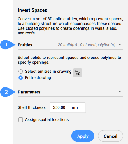
- Entities
- Parameters
- Entities
- Displays the options for selecting the entities to be used as input.
- Select entities in the drawing
- Click on the arrow button to manually select 3D solids and closed polylines.
- Entire drawing
- All the 3D solids and closed polylines in the drawing are used as input.
- Parameters
- Displays the values of the parameters used to create the shell.
- Shell thickness
- Sets the thickness of the external walls created.
- Assign spatial location
- Tick the checkbox to assign spatial locations to the created elements.