CIVILPOINT command
Creates Civil Points.

Icon: 
Description
Civil Points are defined in BricsCAD as Civil entities, which are represented by symbols and labels. The graphical representation of civil points can be defined through Symbol style and Label style. In addition to XYZ coordinates, Civil Points can have a variety of attributes assigned, including point number, next point number, point elevation, point name, raw (field) description and full (expanded) description. You can also add any other attributes to civil points and display them in the point label style.
Use the Properties panel to edit the attributes of an individual point or a group of selected points.
For improved organization, Civil Points can be collected into point groups based on certain criteria determined by filters.
You can use the basic BricsCAD commands to edit Civil Points in a drawing. For example, COPY, COPYCLIP, PASTE, PASTECLIP, MOVE, ROTATE.
You can use Civil Points as input objects for creating a TIN Surface, which is automatically updated when editing points.
Opens the Create Civil Points dialog box.
The Create Civil Points dialog box allows you to create civil points by specifying their position in the drawing, converting CAD points or blocks into civil points, or generating civil points on selected objects.
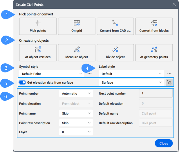
- Pick points or convert
- On existing objects
- Symbol style
- Label style
- Get elevation data from surface
- Point settings
Pick points or convert
Creates civil points by specifying point location or by converting entities in a drawing.
- Pick points
- Allows you to create individual civil points in a drawing by specifying their location.
- On grid
- Allows you to automatically create civil points on a grid. The grid characteristics (origin, x and y spacing, grid rotation, and extent) are requested on the Command line.
- Convert from CAD points
- Allows you to create civil points from selected CAD points.
If selected CAD points have corresponding GIS attributes, the Map Attributes dialog opens, allowing you to map them with Civil points attributes. Select for each property the Civil point data as Name, Raw description, Elevation, or None. By default, None is selected.
Note: Click the magnifying glass icon ( ) to activate the Search bar and search for specific properties.
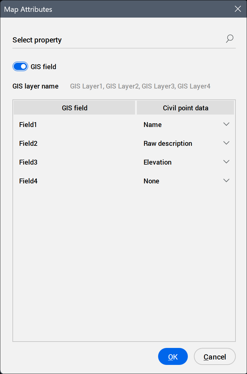
- Convert from blocks
- Allows you to create civil points from selected blocks.
If selected blocks have corresponding block attributes or GIS attributes, the Map Attributes dialog opens, allowing you to map them with Civil points attributes. Select for each property the Civil point data as Name, Raw description, Elevation, or None. By default, None is selected.
Note: Click the magnifying glass icon () to activate the Search bar and search for specific properties.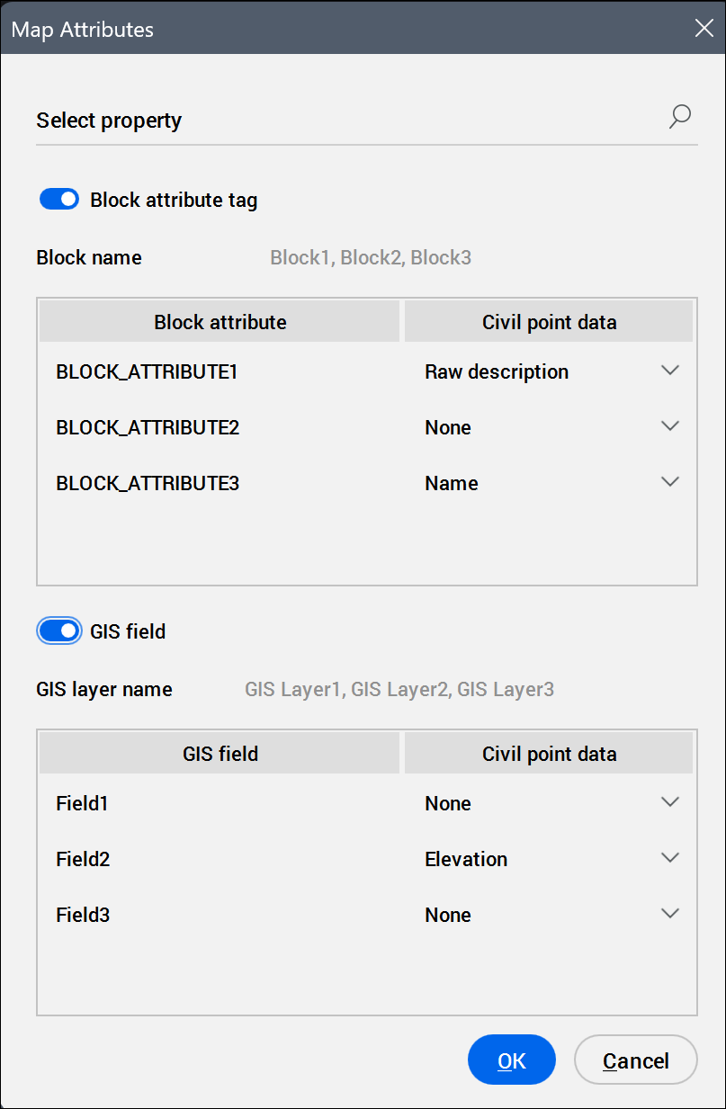
On existing objects
Creates civil points on existing objects.
- At object vertices
- Allows you to create civil points at the vertices of objects.
- Measure object
-
Creates civil points along a selected object by defining the start and end station, offset distance, and segment length. Points can be defined interactively by selecting a position on the object or by entering values in the Command line.
- Start at station
- Specifies the start station point. The default value is 0.
- End at station
- Specifies the end at station point. The default value is the total length of the object.
- Specify offset
- Specifies the offset of civil points from the selected object. Negative values place the civil points on the other side of the object.
- Specify segment length.
- Specifies the spacing (segment length) between civil points created on the selected object.
- Divide object
-
Creates civil points on a selected object by specifying the number of segments and the offset from the object. The points are placed at equal spacing along the object, based on the defined number of segments.
- Enter number of segments
- Sets the number of segments.
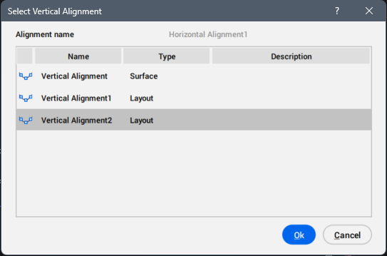
- At geometry points
- Creates Civil points along an Alignment. When the Horizontal Alignment includes a Vertical Alignment and the Point elevation attribute is set to From object, the Select Vertical Alignment dialog box opens. This allows you to set the elevations for civil points on the selected Vertical Alignment.
Symbol style
Allows you to select the symbol style from the drop-down list of defined styles.
Click the Browse button ( ) to open the Select Style dialog box, where you can edit the current style or create a new one by copying an existing style.
Label style
Allows you to select the label style from the drop-down list of defined styles.
Click the Browse button () to open the Select Style dialog box, where you can edit the current style or create a new one by copying an existing style.
Get elevation data from surface
When turned on, the elevation for the civil points is taken from the selected surface. You can choose an available surface from the drop-down list or click the ( ) button to select it from the drawing area.
Point settings
Allows you to specify the settings for the civil points.
- Point number
- Allows you to specify a number for the civil point.
- Automatic
- Automatically assigns a civil point number based on the value of the Next point number and the numbers already assigned.
- Prompt
- Allows you to specify an initial civil point number on the Command line.
- Point elevation
- Allows you to specify an elevation for the civil points.
- Automatic
- Automatically assigns a civil point elevation based on the value of the Default elevation.
- Prompt
- Allows you to define the civil point elevation on the Command line.
- Undefined
- Sets an undefined civil point elevation.
- From object
- Gets the elevation for civil point from a selected object.
- Point name
- Allows you to define a name for the civil point.
- Automatic
- Automatically assigns a civil point name.
- Prompt
- Allows you to define the civil point name on the Command line.
- Skip
- Allows you to not set a name for the civil point.
- Point raw description
- Allows you to specify a description for the civil point, which contains multiple parts, such as words, letters, numbers, symbols, separated by spaces. Note: When the slash (/) character is used instead of a space, the name is treated as a single part.
Example:
- SP/RAILROAD XING – name consists of two parts: SP/RAILROAD and XING
- SP/NO PARKING – name consists of two parts: SP/NO and PARKING
- MISC/DOT BOX 30 – name consists of three parts: MISC/DOT, BOX, 30
- LINE ST JPN 2 – name consists of four parts: LINE, ST, JPN, 2
- CPS/4" SOLID YELLOW – name consists of three parts: CPS/4", SOLID, YELLOW
- Layer
- Allows you to set the layer for the civil points.
- Next point number
- Allows you to define a starting number for a range of civil points. This supports multiple ranges of point numbers within the same drawing.
- Default elevation
- Allows you to set a default elevation for civil points.
- Default name
- Allows you to set a default name for civil points.
- Default raw description
- Allows you to set a default raw description for the civil points.