POINTCLOUDPROJECTSECTION command
Automatically generates a 2D raster image with optional contour lines from a defined section box.
Icon: 
Method
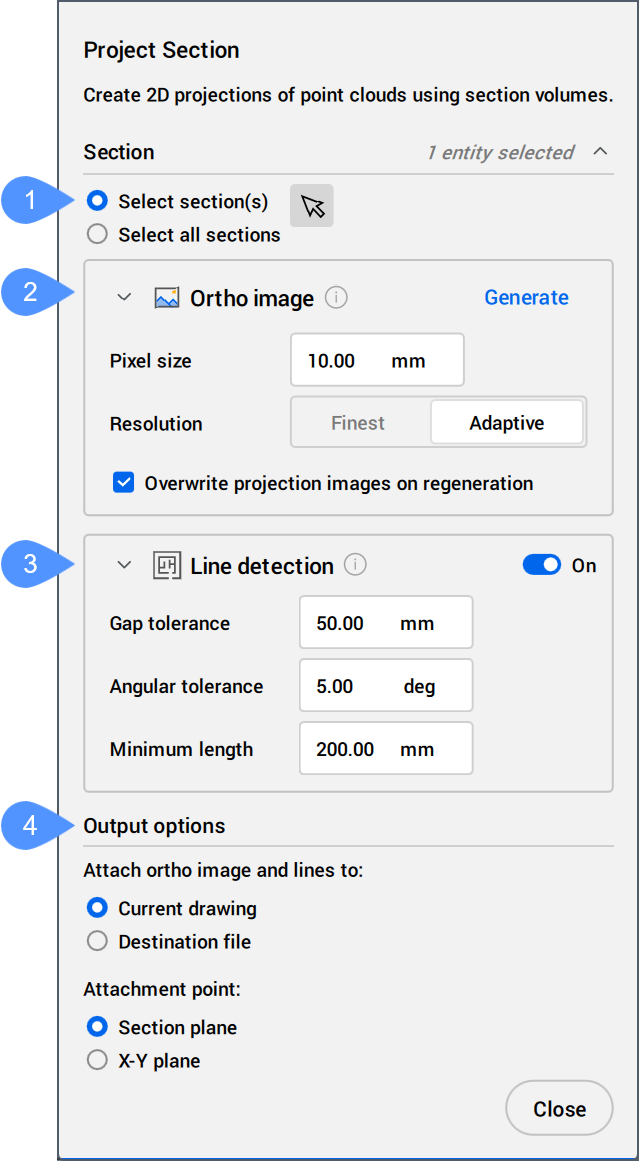
The Project Section command context panel is automatically displayed when running the command.
Make a section selection, decide whether to generate lines alongside the raster image, set the parameters, and then click the Generate option.
Note: The options within the command context panel reflect those within the Command line.
Options within the command context panel
- Section selection
- Ortho image
- Line detection
- Output options
- Section selection
- Allows you to select BIM sections of any state to project.
-
- Select section(s)
- Click the Select arrow (
 ) and pick a section in the drawing.
- Select all sections
- All sections in the drawing are automatically selected.
- Ortho image
-
- Generate
- Becomes available once a section is selected. Generates a 2D raster image from a point cloud section.
- Pixel size
- Controls the pixel size of the generated image.
- Resolution
- Determines the resolution of the projection. Allows you to switch between Finest and Adaptive.
- Overwrite projection images on regeneration
- If checked, overwrites any old image files on disk related to the section.
- Line detection
- If On, automatically creates lines or 2D polylines along the intersection of the point cloud with the section plane.
Allows you to modify the parameters that control the 2D line generation with a live preview.
- Gap tolerance
- Controls the search area for the algorithm to draw lines. Gaps smaller than the specified value will be closed.
- Angular tolerance
- Controls the angular tolerance of the generated lines. A high tolerance results in pronounced right angles. This is useful for perpendicular plans.
Generated lines with a smaller angle than the specified value are merged.
- Minimum length
- Controls the minimum length of a generated line. Lines with a smaller length than the specified value are not generated.
- Output options
-
- Attach ortho image and lines to
- Determines where the resulting image is generated.
Allows you to switch between Current drawing and Destination file.
- Attachment point
- Determines the insertion point for the generated image.
Allows you to switch between Section plane and X-Y plane.
Options within the command line
- reMove old
- Defines whether to remove or keep previously added images or lines.
- Yes
- Removes previously added images or lines to the section.
- No
- Keeps previously added images or lines to the section.