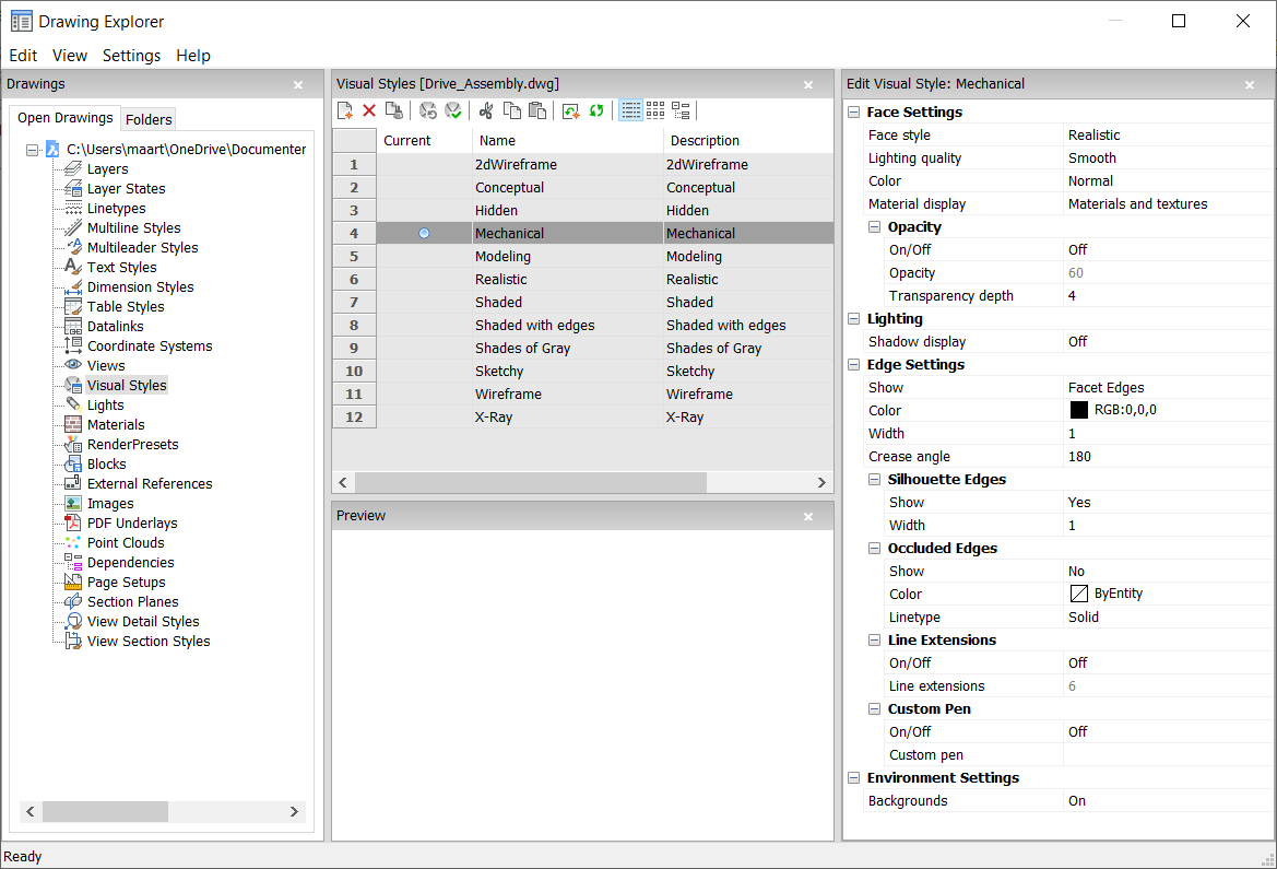
VISUALSTYLES command
Opens the Drawing explorer dialog box with Visual Styles selected.

Icon: 
Method
Opens the Drawing explorer dialog box with Visual Styles category selected to view and modify visual styles in the current drawing.

- Reset to default (
 )
) - Restores the original settings for predefined visual styles.
- Apply visual style (
 )
) - Applies the selected visual style to the current viewport.
- Edit visual style
- Displays the settings of the selected visual styles. To edit a setting: click the settings field, then type a new value or select an option in the drop down list.
- Face Settings
- Specifies the look of faces of 3D models.
- Face style
- Selects an overall color scheme for the visual style.'
- Lighting quality
- Specifies the quality of curved faces.
- Color
- Selects the color mode.
- Material display
- Determines whether materials are displayed. Materials are applied with the MATERIALASSIGN command.
When Material Display is not off, then highlights and opacity are ignored, as materials provide their own values for them.
- Opacity
- Specifies the level of transparency of faces.
- On/Off
- Toggles the opacity on and off.
- Opacity
- Specifies the level of transparency (not available when materials are on).
- Transparency depth
- Specifies how far transparency reaches in terms of the number of overlapping entities.
- Lighting
- Determines whether shadows are displayed.
- Shadow display
- Specifies how shadows are displayed:
- Off: objects cast no shadows, the preferred option as shadow-casting slows down the program's display speed, so leave it turned off unless you are saving images to file or plotting them.
- Ground shadows: objects cast shadows on the shadow plane, but not on each other
- Mapped object shadows: objects cast shadows on the ground and on each other
- Edge Settings
- Specifies the style of edge to display.
- Show
- Specifies how edges are displayed.
- None: neither facets nor isolines nor edges are displayed; this setting turns off many other settings.
- Isolines: isolines and edges are displayed; isolines are the curved lines that simulate the surfaces of curved faces.
- Facet Edges: facets and edges are displayed on entities.
- Color
- Specifies the color for all edges.
- Width
- Specifies the width of edge lines.
- Number of lines
- Specifies the number of isolines drawn on curved surfaces, from 0 to 2047.
- Always on top
- Determines if all isolines are displayed, or only those that are "on top" (hidden isolines being hidden).
- Silhouette Edges
- Determines how fat outlines are around models.
- Show
- Toggles the display of silhouette edges.
- Width
- Specifies the width of the silhouette edges in the range of 1 to 25 pixels; applies to all entities in the viewport equally.
- Occluded Edges
- Specifies how to handle occluded (hidden) edges and facets; this setting allows you to display hidden lines in a different color and linetype from visible lines.
- Show
- Toggles the visibility of occluded edges and facets.
- Color
- Specifies the color for visible obscured edges and facets. Click Select color... to select another color from the Color dialog box.
- Linetype
- Specifies the line type for visible obscured edges and facets. The program does not use the usual linetype patterns, but a separate set. All these settings do not apply to isolines.
- Line Extensions
- Extends edges beyond their boundaries, also known as "overhang".
- On/Off
- Turn line extensions on or off.
- Line extensions
- Specifies the distance over which the lines extend beyond boundaries, such as face edges.
- Custom Pen
- Determines the use of a custom line drawing style.
- On/Off
- Turn the drawing style on or off.
- Custom pen
- Specifies the style of line drawing.
- Environment Settings
- Toggles the display of a background in the viewport.
Backgrounds consist of either a solid color, a gradient of two or three colors, or a raster image, and are set by the BACKGROUND command.
Note: The ANTIALIASSCREEN system variable controls the amount of anti-aliasing (edge smoothing) applied during on-screen rendered mode display. The default value is 1, maximum value is 5. High anti-alias values incur a high calculation cost.
Context Menu Options
- New
- Creates a new visual style.
- Delete
- Deletes the selected visual style, except for predefined visual styles such as 2dWireframe, 3D Hidden, 3dWireframe, Conceptual, Realistic…
- Reset to default
-
Restores the selected visual style(s) to default.
- Apply to current viewport
- Applies the selected visual style to the current viewport.
- Rename
- Renames the selected visual style.
- Select All
- Selects all visual style definitions.
- Invert Selection
- Deselects the current selection and vice versa.

