Piezas estándar
Visión general
Utilice el comando LIBRARYPANELOPEN.
BricsCAD cuenta con una biblioteca de más de 1.000 piezas mecánicas estándar disponibles en más de 170.000 tamaños diferentes. Están disponibles en el panel Biblioteca y se pueden arrastrar y soltar desde la biblioteca hasta su ensamblaje. Puede ajustar los parámetros en el panel de Propiedades , que temporalmente lista los parámetros del bloque mecánico que se está insertando. Después de la inserción, los parámetros se pueden editar en el Navegador Mecánico y en el panel Propiedades .
- Piezas estándar
- Agujeros
- Chapa Metálica
- Herramientas
Piezas estándar
- Sujetadores, como pernos, tuercas y arandelas.
- Piezas de máquinas, como rodamientos y piñones.
- Tuberías, como tuberías, codos y bridas.
- Formas estructurales, como vigas, canales y barras.
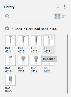
El contenido de cada subcategoría está estructurado por tipo, subtipo y estándares.
Ejemplo: Piezas estándar / Sujetadores / Pernos / Pernos de cabeza hexagonal / ISO / ISO 4017.
- Representación de rosca (THREADDISPLAY) se utiliza para representar (o no representar) una rosca 3D para tornillos y tuercas. Este ajuste permite disminuir el consumo de memoria y aumentar el rendimiento de los ensamblajes grandes
- El número máximo de dientes de la rueda dentada (GEARTEETHNUMBER) se utiliza para limitar el número de dientes para las ruedas dentadas (disponible en Piezas estándar / RUEDA DENTADA). Este ajuste permite disminuir el consumo de memoria y aumentar el rendimiento.
De forma predeterminada, THREADDISPLAY se establece en Desactivado y GEARTEETHNUMBER se establece en 1, para optimizar el rendimiento del modelo. Cuando se modifica, la configuración se aplica a todos los documentos nuevos.
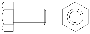
Representación estándar del hilo en las vistas de dibujo
Las vistas de dibujo de sus ensamblajes, generadas con el comando VIEWBASE, contienen anotaciones de hilo para piezas estándar como líneas finas para vistas laterales y como un arco delgado de 270 grados para vistas superior/inferior.
Ejemplo:
Agujeros
La categoría Orificios contiene una biblioteca paramétrica de taladros estándar, como ranuras, avellanados y orificios con fondo plano.
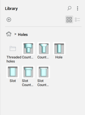
También hay una subcategoría de Orificios roscados, representados en las vistas de dibujo.
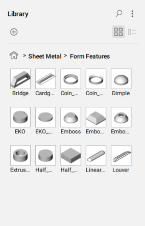
Características de la forma de chapa
La categoría Chapa metálica contiene una biblioteca paramétrica de características de forma de chapa metálica, como puentes y relieves.
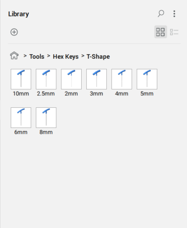
Herramientas
- Llave hexagonal, como llave hexagonal en forma de L y en forma de T
- Llaves Dinamométricas
- Llaves Ajustables, como llaves de combinación y de trinquete
- Destornillador
Ejemplo: Herramientas / Llaves hexagonales / en forma de T
Coloca una pieza estándar en el dibujo actual
- Elige una categoría.
- Elija un estándar.
- Seleccione un tipo.
- Haz clic en la parte estándar deseada.
- Edite los parámetros en el panel Propiedades .
- Haz clic en el área de dibujo para insertar la pieza seleccionada como bloque mecánico.
Como la mayoría de las piezas estándar son bloques mecánicos, puedes editarlas usando el comando EDITARBLOQUE. Además, es posible asignar estándar, categoría, tipo y descripción para piezas estándar personalizadas, y anular esas propiedades para las piezas suministradas con BricsCAD.
En las tablas BOM, las partes estándar con el mismo nombre y parámetros se tratarán como iguales y pares.
Crea tu propia pieza estándar
Utilice el comando CREATELIBRARYBLOCK para crear sus propias piezas estándar y añadirlas al panel Biblioteca .
Controlar la visualización de los hilos
- Abra el cuadro de diálogo Configuración.
- Vaya a la variable Representación de rosca (THREADDISPLAY).
- Activa la configuración.
- Si corresponde, actualice el documento para que aparezcan hilos en las piezas existentes:
- Establezca temporalmente el modo de actualización de componentes de ensamblaje (BMUPDATEMODE) en [1] Actualizar todos los componentes.
- Utilice el comando BMUPDATE para actualizar el documento.
- Si procede, establezca el modo de actualización de componentes de ensamblaje (BMUPDATEMODE) en el valor anterior.
Controlar el número de dientes de cría
- Abra el cuadro de diálogo Configuración.
- Vaya a la variable Número máximo de dientes de rueda dentada (GEARTEETHNUMBER).
- Establezca el valor para que sea suficiente para las ruedas dentadas usadas (se recomienda 500).Nota: Los valores más grandes ralentizan la actualización de los cohetes estándar. Si el valor es menor que el número requerido, solo se muestra ese número de dientes de cría.
- Si procede, actualice el documento para que los dientes de los piñones aparezcan en las piezas existentes:
- Establezca temporalmente el modo de actualización de componentes de ensamblaje (BMUPDATEMODE) en [1] Actualizar todos los componentes.
- Utilice el comando BMUPDATE para actualizar el documento.
- Si procede, establezca el modo de actualización de componentes de ensamblaje (BMUPDATEMODE) en el valor anterior.