Przepływ pracy elastycznego wstawiania naprowadzanego
Wprowadzenie
Krzywe odniesienia są specyficznymi elementami bloku parametrycznego 2D. Służą one do wyrównania bloku z elementami na rysunku docelowym.
Krzywe odniesienia mogą być sparametryzowane. Oznacza to, że nie tylko blok można wyrównać do elementów na rysunku docelowym, ale także rozmiar i wygląd bloku można dostosować do konfiguracji elementów na rysunku docelowym.
Proces wstawiania bloku ze sparametryzowanymi krzywymi odniesienia do rysunku nazywany jest Elastyczne wstawianie naprowadzane.
Schemat
Przepływ pracy procesu Elastyczne wstawianie naprowadzane jest następujący:
- Utwórz nowy rysunek dla definicji bloku.
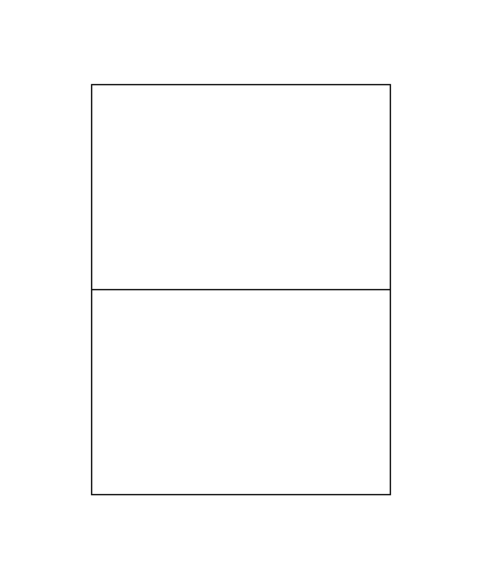
- Utwórz obiekt bloku. W tym przypadku użyty zostanie prosty prostokątny symbol. Patrz zdjęcie poniżej:
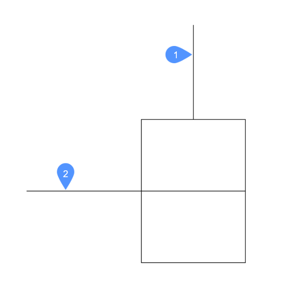
- Utwórz jednostki, które będą używane jako krzywe odniesienia, jak na poniższym obrazku. W tym przypadku dodawane są linie oznaczone cyframi 1 i 2, które zostaną wykorzystane w następnym kroku.
- Zdefiniuj krzywe odniesienia. Krzywe te nie są częścią krzywych szczegółowych, ale będą używane jako odniesienie dla wstawienia (tj. krzywe odniesienia).Linie oznaczone cyframi 1 i 2 (z poprzedniego kroku) zostaną przekształcone w krzywe referencyjne za pomocą polecenia KRZYWEODNIESIENIA. Polecenie to można uruchomić, wpisując KRZYWEODNIESIENIA w wierszu poleceń lub używając przycisku Krzywe odniesienia na karcie Operacje na wstążce.Aby zdefiniować krzywe odniesienia, uruchom polecenie KRZYWEODNIESIENIAi wybierz linie 1 i 2.Po uruchomieniu polecenia rysunek będzie wyglądał następująco:
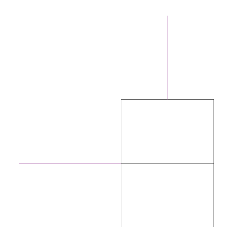 Dwie linie zostały przekształcone w krzywe odniesienia. Ich kolor został zmieniony na fioletowy i zostały one przeniesione na specjalną warstwę o nazwie KRZYWE_ODNIESIENIA. Warstwa ta jest tworzona automatycznie przez polecenie.
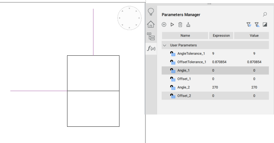
 - Aby sparametryzować krzywe referencyjne, uruchom polecenie KRZYWEODNIESIENIA i wybierz opcję PARAMETRYZUJ. Ta opcja utworzy parametry kontrolujące konfigurację krzywych odniesienia. Parametry te mogą być teraz (opcjonalnie) używane w wyrażeniach ręcznie dodawanych ograniczeń (np. w celu przymocowania krzywych odniesienia do elementów szczegółowych).Parametry można przeglądać w panelu Menedżera parametrów, jak na poniższej ilustracji.
- Zapisz blok.
- Otwórz rysunek docelowy i wstaw blok.Rozmyte zachowanie wstawiania można uzyskać za pomocą polecenia WSTAW (z włączoną opcją Użyj krzywych odniesienia do wstawienia ) lub przeciągając i upuszczając blok ze sparametryzowanymi krzywymi referencyjnymi z biblioteki do bieżącej przestrzeni modelu.Krzywe odniesienia bloku powinny być prawidłowo dostosowane i odwzorowane do sytuacji docelowej. Przesuń mysz do miejsca, w którym chcesz przyciągnąć blok i kliknij, aby go umieścić.Oto prosty rysunek pokazujący, jak działa funkcja Elastyczne wstawianie naprowadzane:

Po uruchomieniu polecenia WSTAW(z włączoną opcją Użyj krzywych odniesienia do wstawienia ) blok zostanie załadowany do kursora myszy.
Gdy kursor myszy zostanie umieszczony w pobliżu elementów na rysunku, które mogą pasować do krzywych odniesienia, blok zostanie przyciągnięty do tych elementów, jak na poniższych ilustracjach:
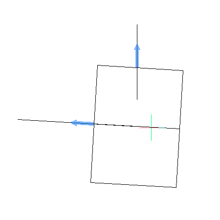
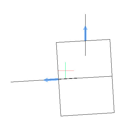
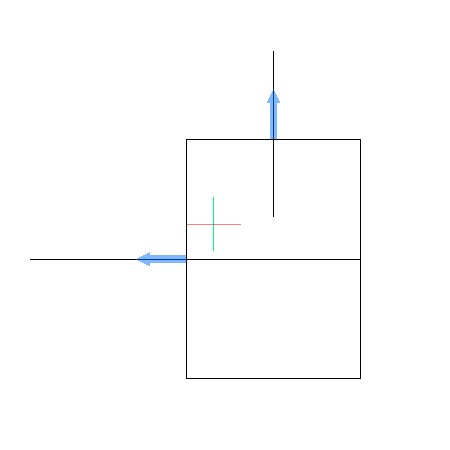
Gdy kursor myszy (z dołączonym blokiem) nie znajduje się wokół żadnych elementów lub elementy nie pasują do krzywych odniesienia, przyciąganie nie występuje, jak na poniższym obrazku:
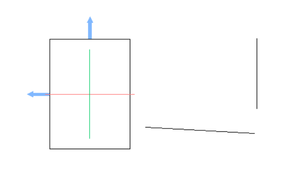
W takim przypadku blok można wstawić do rysunku w normalny sposób.

