DIMALIGNED command
Creates an aligned dimension.

Icon: 
Alias: DAL, DIMALI
Description
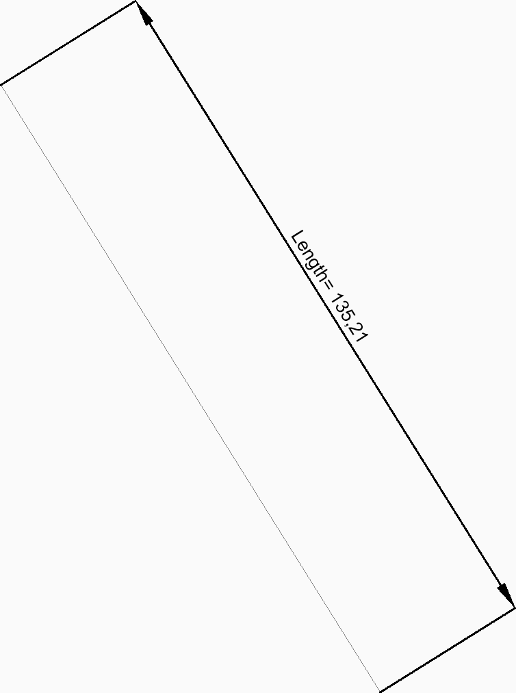
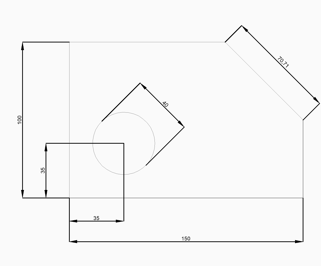
Creates a dimension that aligns with the origin points of the extension lines. The dimension is based on the current dimension style. Options allow you to specify the angle and contents of the dimension text.
Note: Isometric view can be dimensioned and reflect the actual true geometry size.
Method
This command has 2 methods to begin creating an aligned dimension:
- Origin of first extension line
- Select entity
Options within the command
- Origin of first extension line
- Allows you to begin creating an aligned dimension by specifying a point for the first extension line.
- Origin of second extension line
- Allows you to specify a point for the second extension line.
- Location of dimension line
- Specifies the location of the dimension line. The dimension is placed at the same distance from each of the extension line origins.
- Origin of first extension line
- Origin of second extension line
- Location of dimension line
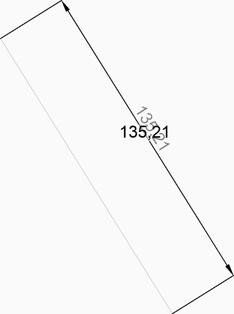
- Aligned dimension
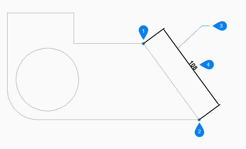
- Select entity
- Allows you to select a line, polyline segment, arc, or circle to dimension.Note:
- When selecting a line, the endpoints of the line are used for the extension origins.
- When selecting an arc, the endpoints of the arc are used for the extension origins.
- When selecting a circle, the selection point on the circle is used for the first extension origin and the opposite point on the diameter of the circle is used for the second extension origin.
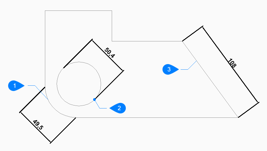
- Arc entity
- Selection point of circle entity
- Polyline entity
- Angle
- Specifies the angle of the dimension text. A value of 0 aligns the dimension text with the dimension line. Any other value rotates the dimension text relative to the x-axis of the current UCS.
- Text
- Enter text to override the default dimension text which includes the measured length of the dimension. You can use two angle brackets <> to display the measured length of the dimension in addition to other text.