BIMTRAVE
Crea solidi classificati come Trave.

Icona: 
Descrizione
Il comando crea travi con forme diverse. È possibile definire le opzioni tramite il pannello del contesto dei comandi e tramite la Barra dei comandi.
Metodo
Avviare il comando per aprire il pannello contesto comandi Trave.
Nota: Per posizionare le travi più facilmente, attivare la Modalità Vista dall'Alto (TVM) prima di avviare il comando cliccando su un disco del piano ( ) nella Barra dei Piani (vedere l'articolo La Barra dei Piani). Assicurarsi che il piano della sezione superiore sia posizionato sopra la trave.
) nella Barra dei Piani (vedere l'articolo La Barra dei Piani). Assicurarsi che il piano della sezione superiore sia posizionato sopra la trave.Esistono due metodi per creare travi:
- Posizionamento di travi singole, vincolate dall'asse X/Y
- Disegnare travi multiple, non vincolate dall'asse X/Y.
Utilizzare le quote dinamiche per definire il punto di inserimento di una trave singola in modo più accurato. Queste dimensioni mostrano le distanze dalla singola trave alle pareti e/o alle travi. Premere il tasto TAB per passare da una quota all'altra e impostarle manualmente.
Nota: Le quote dinamiche vengono visualizzate se Input Dinamico (DYN) è impostato su On (vedere l'articolo Quote dinamiche).
Utilizzare il widget Assistente Tasti di scelta rapida per modificare la direzione della singola trave corrente. Premere il tasto Ctrl per passare dall'opzione Trave allineata a X a Trave allineata a Y.

Nota: Il widget Assistente Tasti di scelta rapida viene visualizzato se la variabile di sistema HOTKEYASSISTANT è impostata su 1 e la casella di controllo Visualizza Suggerimenti Tasti di Scelta Rapida per le opzioni di BIMTRAVE è selezionata nella finestra di dialogo Configurazione di Assistente Tasti di scelta rapida (vedere l'articolo widget Assistente Tasti di scelta rapida).
Opzioni all'interno del pannello contesto comando
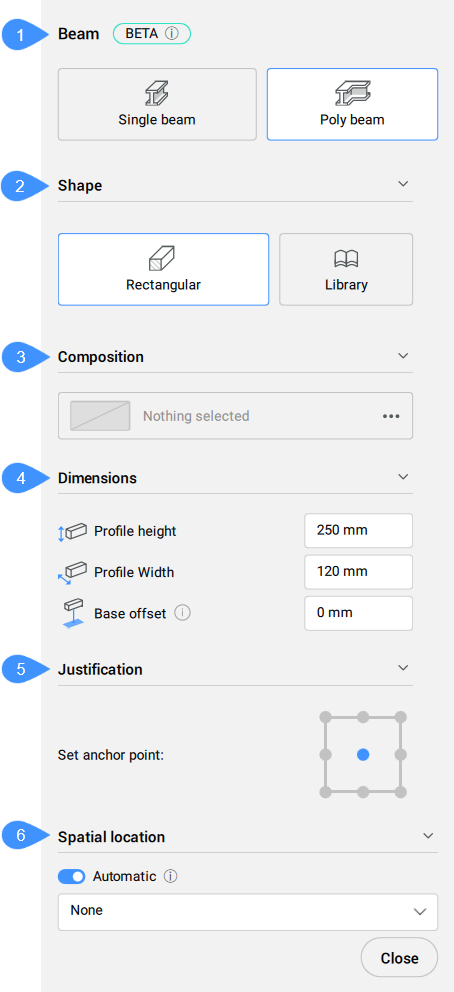
- Modalità creazione
- Forma
- Composizione
- Quote
- Giustificazione
- Localizzazione spaziale
- Modalità creazione
- Scegliere un metodo per creare la trave o le travi correnti.
- Forma
- Definisce il profilo della trave corrente. È possibile selezionare un profilo esistente o crearne uno nuovo.
- Composizione
- Cliccare sul pulsante Sfoglia (
 ) per aprire la finestra di dialogo Composizioni che consente di definire la composizione della trave corrente. Qui è possibile modificare il tipo di composizione selezionando un nuovo filtro dal menu a discesa in alto a sinistra.
- Quote
-
- Altezza del profilo/Larghezza del profilo
- Imposta l'altezza/larghezza del profilo.Nota: Queste opzioni sono disponibili solo per il profilo Rettangolare.
- Giustificazione
- Ci sono nove punti di giustificazione: Alto-Sinistra, Alto-Centro, Alto-Destra, Mezzo-Sinistra, Mezzo-Centro, Mezzo-Destra, Basso-Sinistra, Basso-Centro, Basso-Destra. Per impostazione predefinita, il punto di ancoraggio è impostato al mezzo-centro. Per modificarlo, cliccare su un altro punto di ancoraggio visualizzato.
- Localizzazione spaziale
- Consente di selezionare una posizione spaziale dal menu a discesa da assegnare alla trave.
Nota: Le opzioni all'interno del pannello contesto comandi e quelle all'interno del widget Assistente Tasti di scelta rapida riflettono le opzioni all'interno della Barra dei comandi.