


Customize dialog box
Opens via: CUI command
The Customize dialog box allows you to customize the user interface of BricsCAD®.
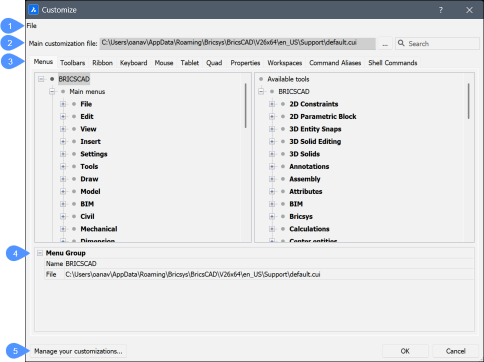
- File
- Main customization file
- Tab options
- Menu Group
- Manage your customizations
File
Shows a menu to select customization files or import workspaces.
- Load main CUI file...
- Opens the Select main CUI file dialog box to select a customization file. See the CUILOAD command.
- Save main CUI file as...
-
Opens the Save main CUI file as dialog box to save the current main CUI file.
Note: You can save the main CUI file under a different name to copy the adapted main CUI file.
- Load Partial CUI file...
-
Opens the Choose a Customization File dialog box to open a partial CUI file.
Note: See chapter Loading a partial CUI file in Loading and unloading CUI files for a detailed explanation about the partial CUI files.
- Create new partial CUI file...
- Opens the Create a Customization File dialog box to create an empty CUI file.
- Import workspace(s)…
- Opens the Choose a Customization File dialog box to load one or more workspaces from another CUI file.
Main customization file
Specifies the CUI file that defines customization of the menu, toolbar, and other elements of the user interface.
- Browse
- Opens the Select main CUI file dialog box to load a different main CUI file.
- Search
- Searches the Available Tools list for command names.
Tab options
- Menus
-
Adds, edits, moves and deletes menu items.
When right clicking a menu, menu item or submenu in the Menus tab, a context menu opens. See the paragraph Options Within the Context Menu for further explanation.
Note: If you select Append item or Insert item from the context menu, the Add menu item dialog box displays.- Menu Group/Menu/Menu Item/Submenu
- Displays the options of the selected menu, submenu or menu item.
- Title
- Specifies the name that is displayed by the menu, menu item or submenu.Note: You can prefix a letter with ‘&’ to create an Alt-key shortcut. For example: &Line.
- ID
- Unique identifier for each Menu item. (The ID is assigned by BricsCAD®).
- Alias
- Defines the aliases of the menu. The browse icon opens the Edit Aliases dialog box where you can edit, create or delete aliases.
- Diesel
- Specifies the Diesel code to be employed by the menu item or submenu.
- Tool ID
- Identifies the menu item or sub menu to other elements in the CUI file. (The Tool ID is assigned by BricsCAD®).
- Help
- Specifies the help string displayed on the status bar.
- Command
- Specifies the command(s) or macros.
- Image
- Specifies the image to display for the menu item or submenu. The browse icon opens the Tool Image dialog box. There are five options to select an image.
- Toolbars
-
Adds, moves and deletes toolbar items.
When right clicking a toolbar, tool, control, flyout or separator in the Toolbars tab, a context menu opens. See the paragraph Options Within the Context Menu for further explanation.
Note: If you select Append tool or Insert tool from the context menu, the Add tool dialog box displays. For options description, see the Add menu item dialog box.- Menu Group/Toolbar/Toolbar Button
- Displays the options of the selected toolbar, toolbar button, toolbar control or toolbar flyout.
- Title
- Specifies the name that is displayed by the tooltip.
- ID
- Unique identifier for each toolbar item. (The ID is assigned by BricsCAD®).
- Alias
- Defines the aliases of the selected item. The browse icon opens the Edit Aliases dialog box where you can edit, create or delete aliases.
- Position
- Specifies the position of the selected toolbar. You can choose between Floating, Top, Left, Bottom, Right.
- Default Display
- Determines whether the selected item will be added to the workspace.
- Rows
- Specifies the number of rows for an undocked toolbar.
- Xval Yval
-
Specifies the distance in pixels measured from the top left corner of the screen to the toolbar. It applies to undocked toolbars.
The values are taken from the X,Y options of the toolbar as they are set in the Workspace tab.
- Diesel
- Specifies the Diesel code to be employed by the selected item.
- Tool ID
- Identifies the toolbar item to other elements in the CUI file. (The Tool ID is assigned by BricsCAD®).
- Help
- Specifies the help string displayed on the toolbar.
- Command
- Specifies the command(s) or macros.
- Image
- Specifies the image to display for the toolbar button. The browse icon opens the Tool Image dialog box. There are five options to select an image.
- Ribbon
-
Manages the ribbons and/or adds panels to a ribbon tab.
When right clicking a ribbon tab or panel in the Ribbon tab, a context menu opens. See the paragraph Options Within the Context Menu for further explanation.
Note: If you select Add launcher, Insert toggle button or Insert command button from the context menu, the Add ribbon dialog launcher, Add ribbon toggle button or Add ribbon command button dialog boxes display:- Select available tool: assigns an existing command to the new item. If this option is selected, the other options are grayed out, except for Available tools.
- Create new tool: assigns a new command/macro to the new item. If this option is selected, Available tools is grayed out.
- Toolbox: specifies the toolbox to which to add the new command. You can choose a toolbox in the drop down list.
- Title: specifies the name of the new tool.
- Help: specifies the help string displayed on the status bar.
- Command: specifies the command(s) or macros.
- Image: specifies the image to display for the new tool. The browse icon opens the Tool Image dialog box. There are five options to select an image
- Available tools: selects an existing tool.
- Menu Group/Ribbon Tab/Ribbon Panel Reference
- Displays the options of the selected Ribbon Tab or Ribbon Panel Reference.
- ID
- Identifies the item in the CUI file. (The ID is assigned by BricsCAD®).
- Collapse
- Allows you to choose if the panel will collapse automatically or if it will never collapse.
- Label
- Specifies the name that is displayed by the selected Ribbon Tab or Ribbon Panel Reference.
- Title
- Specifies the name of the selected Ribbon Tab or Ribbon Panel Reference.
- Key Tip
-
Note: Ribbon keytips are not yet implemented in BricsCAD®.
- Menu Group/Ribbon Panel/Split Button/Ribbon Row Panel/Command Button/Toggle Button
- Displays the options of the selected Ribbon Panel, Split Button, Ribbon Row Panel, Command Button or Toggle Button.
- ID
- Identifies the item in the CUI file. The ID is assigned by BricsCAD®.
- Label
- Specifies the name that is displayed by the selected Ribbon item.
- Title
- Specifies the name of the selected Ribbon Panel.
- Button Style
- Specifies the display mode for the selected button. You can choose between Small with text, Small without text, Large with text (vertical), Large with text (horizontal) and Large without text.Note: The icon size for the small options is 16×16 pixels, while for the large options is 32×32 pixels.
- Behavior
- Determines how the topmost button behaves when you click on it. You can choose between Drop down, Drop down with recent, Split, Split with recent, Split with recent (static text). The options determine whether the button displays the default command (the first one in the list of buttons), or the most recently used one.Note: Split buttons let you click the upper half to execute the most-recently-used command, or lower half to display the drop-list (flyout).
- List Style
-
Note: This option is not yet implemented in BricsCAD®.
- Grouping
-
Note: This option is not yet implemented in BricsCAD®.
- Image
- Specifies the image to display for the selected Ribbon item.
- Resize Style
-
Note: This option is not yet implemented in BricsCAD®.
- Resize Priority
-
Note: This option is not yet implemented in BricsCAD®.
- Justify Top
-
Note: This option is not yet implemented in BricsCAD®.
- Tool ID
- Identifies the ribbon item to other elements in the CUI file. (The Tool ID is assigned by BricsCAD®).
- Help
- Specifies the help string displayed on the Ribbon.
- Command
- Specifies the command(s) or macros.
- Keyboard
-
Assigns different keyboard shortcuts to different commands.
When right clicking a keyboard shortcut in the Keyboard tab, a context menu opens. See the paragraph Options Within the Context Menu for further explanation.
Note: If you select Append shortcut or Insert shortcut from the context menu, the Add keyboard shortcut dialog box displays.- Select available tool: assigns an existing command to the new keyboard shortcut. If this option is selected, the other options are grayed out, except for Available tools.
- Create new tool: assigns a new command/macro to the shortcut. If this option is selected, Available tools is grayed out.
- Toolbox: specifies the toolbox to which to add the new command. You can choose a toolbox in the drop-down list.
- Title: specifies the name of the new tool.
- Help: specifies the help string displayed on the status bar.
- Command: specifies the command(s) or macros.
- Image: specifies the image to display for the new tool. The browse icon opens the Tool Image dialog box. There are five options to select an image.
- Available tools: selects an existing tool.
- Mouse
-
Modifies the different actions that are connected to the mouse buttons.
When right clicking a button or button group in the Mouse tab, a context menu opens. See the paragraph Options Within the Context Menu for further explanation.
Note: If you select Append button or Insert button from the context menu, the Add button item dialog box displays.
- Tablet
-
Customizes the tablet options.
When right clicking a button or button group in the Tablet tab, a context menu opens. See the paragraph Options Within the Context Menu for further explanation.
Note: If you select Append button or Insert button from the context menu, the Add button item dialog box displays.
- Quad
-
Adds commands to the quad tab or moves commands to other tabs.
When right clicking a quad tab or quad button in the Quad tab, a context menu opens. See the paragraph Options Within the Context Menu for further explanation.
Note: If you select Append quad button or Insert from the context menu, the Add quad button dialog box displays.- Select available tool: assigns an existing command to the new quad button. If this option is selected, the other options are grayed out, except for Available tools.
- Create new tool: assigns a new command/macro to the new quad button. If this option is selected, Available tools is greyed out.
-
Toolbox: specifies the toolbox to which to add the new command. You can choose a toolbox in the drop-down list.
- Title: specifies the name of the new tool.
- Help: specifies the help string displayed on the status bar.
- Command: specifies the command(s) or macros.
- Image: specifies the image to display for the new tool. The browse icon opens the Tool Image dialog box. There are five options to select an image.
- Available tools: selects an existing tool.
- Properties
-
Edits which properties are shown for different kinds of entities.
Note: These properties will only be shown when the ROLLOVERTIPS system variable is ON.
- Workspaces
-
Controls which menu tabs are visible in different workspaces.
When right clicking an item in the Workspace tab, a context menu opens. See the paragraph Options Within the Context Menu for further explanation.
- Command Aliases
-
Customize aliases and add them to different commands.
When right clicking an item in the Command Aliases tab, a context menu opens. See the paragraph Options Within the Context Menu for further explanation.
Note: If you select Add alias or Edit alias from the context menu, the Add alias or Edit alias dialog box displays where you can add or edit an alias.
- Shell Commands
-
Create and edit shell commands. Shell commands run programs external to BricsCAD®.
When right clicking an item in the Shell Commands tab, a context menu opens. See the paragraph Options Within the Context Menu for further explanation.
Note: If you select Add shell command or Edit shell command from the context menu, the Add shell command or Edit shell command dialog box displays where you can add or edit a shell command.
- Options Within the Context Menu
- The following options appear when you right click on an item:
Manage your customizations
Displays the Manage Customizations dialog box to confirm and reverse changes made to the user interface.