Definicje TIN w poleceniu TINEDYTUJ
Przegląd
W tym artykule opisano definicje/operacje TIN dostępne w poleceniu TINEDYTUJ. Opisuje również okno dialogowe każdej definicji, w którym można modyfikować parametry.

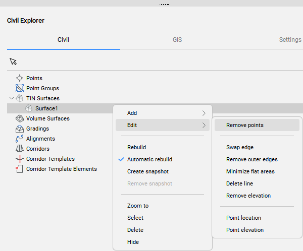
Operacje te są również dostępne w panelu Eksplorator Civil (patrz rysunek poniżej).
Dodaj punkt
Definicja Dodaj punkt tworzy nową powierzchnię TIN lub modyfikuje istniejącą na podstawie określonych lokalizacji i wysokości punktów TIN.
Aby utworzyć definicję Dodaj punkt:
- Wybierz opcję Dodaj Punkty w poleceniu TINEDYTUJ.
- Kliknij prawym przyciskiem myszy istniejącą powierzchnię TIN w oknie Civil Eksplorer i wybierz opcję Wybierz punkty z grupy Dodaj.
Po dwukrotnym kliknięciu definicji Dodaj punkt w zakładce Definicja panelu Civil Eksplorer, otwarte zostanie następujące okno dialogowe.
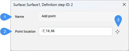
- Nazwa
- Lokalizacja punktu
- Wybierz punkt
- Nazwa
- Wyświetla nazwę definicji powierzchni TIN: Dodaj punkt.
- Lokalizacja punktu
- Wyświetla współrzędne punktu.
- Wybierz punkt
- Umożliwia wybranie nowej lokalizacji i ustawienie nowej wysokości punktu.
Dodaj grupy punktów
Definicja Dodaj grupy punktów dodaje Punkty Civil z określonych Grup punktów do istniejącej powierzchni TIN lub tworzy nową powierzchnię TIN z określonych Grup punktów.
Aby utworzyć definicję Dodaj grupę punktów:
- Wybierz opcję Dodaj Grupy Punktów w poleceniu TINEDYTUJ.
- Kliknij prawym przyciskiem myszy istniejącą powierzchnię TIN w panelu Eksplorator Civil i wybierz Dodaj grupy punktów z grupy Dodaj.
Otworzy się następujące okno dialogowe:
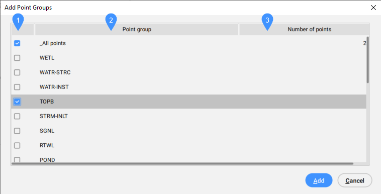
- Pole wyboru
- Grupa punktów
- Liczba punktów
- Pole wyboru
- Umożliwia zaznaczenie lub odznaczenie grupy punktów, która ma zostać uwzględniona.
- Grupa punktów
- Wyświetla listę wszystkich dostępnych grup punktów.
- Liczba punktów
- Wyświetla liczbę punktów w grupie punktów.
Definicja Usuń krawędzie zewnętrzne jest automatycznie dodawana do powierzchni TIN po tej operacji.
Po dwukrotnym kliknięciu tej definicji na karcie Definicje w panelu Civil Eksplorator zostanie otwarte następujące okno dialogowe.
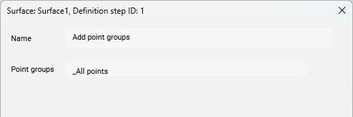
- Nazwa
- Wyświetla nazwę definicji powierzchni: Dodaj grupy punktów.
- Grupy punktów
- Wyświetla listę grup punktów używanych do tworzenia powierzchni TIN.
Dodaj linie nieciągłości
Definicja Dodaj Linie Nieciągłości dodaje wybrane liniowe obiekty CAD do powierzchni TIN jako linie podziału.
Aby utworzyć definicję Dodaj Linie Nieciągłości:
- wybierz opcję Dodaj Linie Nieciągłości w poleceniu TINEDYTUJ.
- Utwórz powierzchnię TIN z liniowych elementów/obiektów CAD i wybierz opcję zastosowania ich jako Linie Nieciągłości.
- Kliknij prawym przyciskiem myszy istniejącą powierzchnię TIN w panelu Eksplorator Civil i wybierz Dodaj linie nieciągłości z grupy Dodaj.
Po dwukrotnym kliknięciu tej definicji na karcie Definicje w panelu Civil Eksplorator zostanie otwarte następujące okno dialogowe.
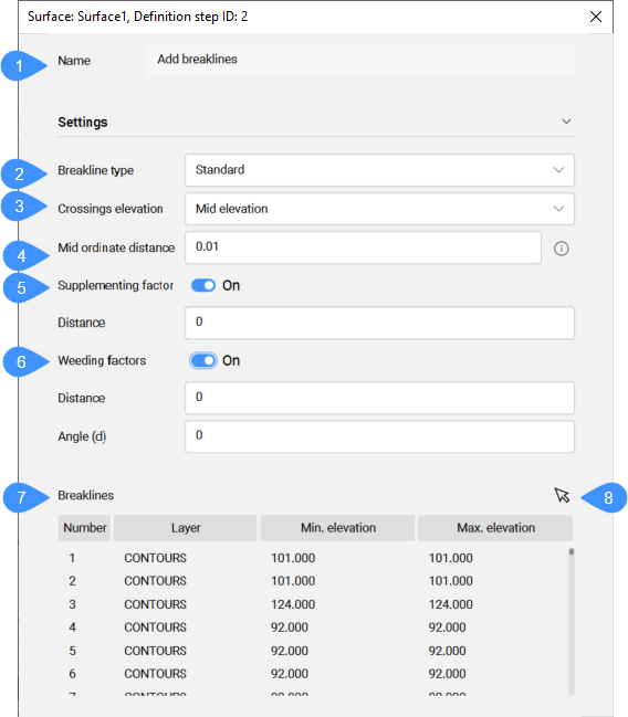
- Nazwa
- Typ linii nieciągłości
- Elewacja przecięć
- Odległość środka cięciwy
- Czynnik uzupełniający
- Czynniki wykluczenia
- Linie nieciągłości
- Przycisk wyboru
- Nazwa
- Wyświetla nazwę definicji powierzchni TIN: Dodaj linie nieciągłości.
- Typ linii nieciągłości
- Wyświetla wybrany typ linii nieciągłości. Wybierz odpowiedni typ linii podziału z listy rozwijanej.
- Elewacja przecięć
- Określa, która wysokość jest brana do triangulacji na przecięciu dwóch linii nieciągłości, dodanych w tej samej definicji Dodaj Linienieciągłości.
- Odległość środka cięciwy
- Dodaje dodatkowe punkty TIN wzdłuż łuku zgodnie ze środkową odległością współrzędnych, która jest używana do aproksymacji łuku.
- Czynnik uzupełniający
- Przełącza użycie czynnika uzupełniającego.
- Czynniki wykluczenia
- Przełącza użycie współczynnika wykluczenia.
- Linie nieciągłości
- Wyświetla linie łamania zawarte w wybranej definicji Dodaj linie nieciągłości.
Tabela zawiera sekwencję Numer, Warstwy, Min. i maksymalna wysokość linii nieciągłości.
Kliknięcie prawym przyciskiem myszy pojedynczej linii łamanej w tabeli oferuje opcję Przybliż do, Wybierz, Usuń lub Kopiuj geometrię do schowka.
- Przycisk wyboru
- Wybiera linię nieciągłości na rysunku, aby zaznaczyć ją w tabeli.
Dodaj granice
Definicja Dodaj granice dodaje wybrane liniowe obiekty CAD do powierzchni TIN jako granice.
Aby utworzyć definicję Dodaj granice:
- Wybierz opcję Dodaj granice w poleceniu TINEDYTUJ.
- Kliknij prawym przyciskiem myszy istniejącą powierzchnię TIN w panelu Eksplorator Civil i wybierz Dodaj granice z grupy Dodaj.
Po dwukrotnym kliknięciu tej definicji na karcie Definicje w panelu Civil Eksplorator zostanie otwarte następujące okno dialogowe.
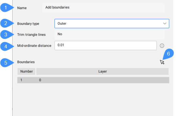
- Nazwa
- Rodzaj granicy
- Przytnij linie trójkąta
- Odległość środka cięciwy
- Granice
- Przycisk wyboru
- Nazwa
- Wyświetla nazwę definicji powierzchni TIN: Dodaj granice.
- Rodzaj granicy
- Wyświetla wybrany typ granicy. Wybierz odpowiedni typ linii podziału z listy rozwijanej.
- Przytnij linie trójkąta
- Wyświetla, czy ten parametr jest używany podczas dodawania granicy do powierzchni TIN.
- Odległość środka cięciwy
- Dodaje dodatkowe punkty TIN wzdłuż łuku zgodnie ze środkową odległością współrzędnych, która jest używana do aproksymacji łuku.
- Granice
- Wyświetla granice dodane w pojedynczej definicji i ich warstwy. Menu kontekstowe oferuje możliwość Przybliżyć do, Wyboru lub Usuń granice.Uwaga: W jednym kroku można dodać wiele granic tego samego typu.
- Przycisk wyboru
- Wybiera granicę na rysunku, aby zaznaczyć ją w tabeli.
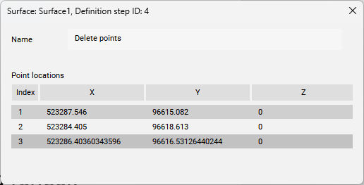
Usuń punkty
Definicja Usuń Punkt usuwa punkty/wierzchołki trójkątów z powierzchni TIN. Możesz usuwać pojedyncze punkty lub wybrać opcję Wiele w wierszu poleceń, aby usunąć wiele punktów jednocześnie.
Aby utworzyć definicję Usuń punkt:
- Wybierz opcję Usuń punkty w poleceniu TINEDYTUJ.
- Kliknij prawym przyciskiem myszy istniejącą powierzchnię TIN w panelu Eksplorator Civil i wybierz opcję Usuń punkty z grupy Edytuj.
Po dwukrotnym kliknięciu tej definicji na karcie Definicje w panelu Civil Eksplorator zostanie otwarte następujące okno dialogowe.
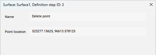
- Nazwa
- Lokalizacja punktu
- Nazwa
- Wyświetla nazwę definicji powierzchni TIN: Usuń punkt.
- Lokalizacja punktu
- Wyświetla współrzędne usuniętego punktu TIN.Uwaga: Jeśli w poleceniu TINEDYTUJ wybrano opcję Wiele (patrz zrzut ekranu wiersza poleceń powyżej), wówczas w oknie dialogowym wyświetlone zostaną współrzędne wszystkich usuniętych punktów TIN.
Zamień krawędź
Definicja Zamień krawędź zamienia wybraną krawędź trójkąta.
Aby utworzyć definicję Zamień krawędź:
- Wybierz opcję Zamień krawędź w poleceniu TINEDYTUJ.
- Kliknij prawym przyciskiem myszy istniejącą powierzchnię TIN w panelu Civil Eksplorator i wybierz opcję Zamień krawędź z grupy Edytuj.
Po dwukrotnym kliknięciu tej definicji na karcie Definicje w panelu Civil Eksplorator zostanie otwarte następujące okno dialogowe.
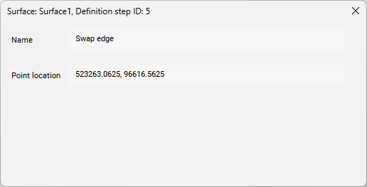
- Nazwa
- Lokalizacja punktu
- Nazwa
- Wyświetla nazwę definicji powierzchni TIN: Zamień krawędź.
- Lokalizacja punktu
- Wyświetla współrzędne XY zamienionej krawędzi.
Przesuń punkt
Ta definicja modyfikuje lokalizację pojedynczego lub wielu punktów TIN w jednym kroku.
Aby utworzyć definicję Przesuń punkt:
- Wybierz opcję Lokalizacja punktu w poleceniu TINEDYTUJ.
- Kliknij prawym przyciskiem myszy istniejącą powierzchnię TIN w panelu Eksplorator Civil i wybierz opcję Lokalizacja punktu z grupy Edytuj.
Po dwukrotnym kliknięciu tej definicji na karcie Definicje w panelu Civil Eksplorer zostanie otwarte następujące okno dialogowe.
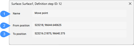
- Nazwa
- Z pozycji
- Do pozycji
- Nazwa
- Wyświetla nazwę definicji powierzchni TIN: Przesuń punkt.
- Z pozycji
- Wyświetla oryginalne współrzędne punktu TIN przed jego przeniesieniem.
- Do pozycji
- Wyświetla nowe współrzędne punktu TIN po przeniesieniu go do nowej lokalizacji.
Modyfikacja wysokości punktu
Ta definicja modyfikuje wysokość pojedynczego lub wielu punktów TIN w jednym kroku.
Aby utworzyć definicję Zmień elewację punktu:
- Wybierz opcję Wysokość punktu w poleceniu TINEDYTUJ.
- Kliknij prawym przyciskiem myszy istniejącą powierzchnię TIN w panelu Eksplorator Civil i wybierz opcję Wysokość punktu z grupy Edytuj.
Po dwukrotnym kliknięciu tej definicji na karcie Definicje w panelu Civil Eksplorer zostanie otwarte następujące okno dialogowe.
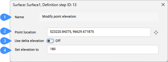
- Nazwa
- Lokalizacja punktu
- Użyj elewacji delta
- Ustaw elewację na
- Nazwa
- Wyświetla nazwę definicji powierzchni TIN: Zmień elewację punktu.
- Lokalizacja punktu
- Wyświetla lokalizację punktu, którego wysokość została zmodyfikowana.
- Użyj elewacji delta
- Umożliwia określenie wysokości delta (różnicy wysokości).
- Ustaw elewację na
- Ustawia nową wysokość dla punktu TIN lub wysokość delta (różnicę wysokości), jeśli włączona jest opcja Użyj wysokości delta.
Dodaj linie
Definicja Dodaj linie dodaje nową krawędź TIN pomiędzy dwoma istniejącymi punktami TIN.
Aby utworzyć definicję Dodaj linie:
- Wybierz opcję Dodaj linie w poleceniu TINEDYTUJ.
- Kliknij prawym przyciskiem myszy istniejącą powierzchnię TIN w panelu Eksplorator Civil i wybierz Dodaj grupy punktów z grupy Dodaj.
Po dwukrotnym kliknięciu tej definicji na karcie Definicje w panelu Civil Eksplorator zostanie otwarte następujące okno dialogowe.
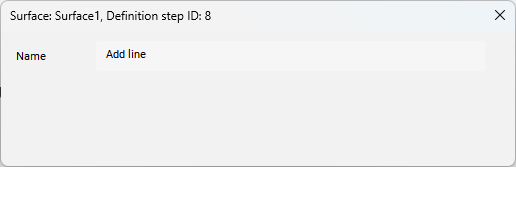
- Nazwa
- Wyświetla nazwę definicji powierzchni TIN: Dodaj linię.
Usuń krawędzie
Definicja Usuń krawędzie usuwa krawędź TIN wewnątrz określonego obszaru zaznaczenia.
Aby utworzyć definicję Usuń krawędzie:
- Wybierz opcję Usuń Linie w poleceniu TINEDYTUJ.
- Kliknij prawym przyciskiem myszy istniejącą powierzchnię TIN w panelu Eksplorator Civil i wybierz Usuń linię z grupy Edytuj.
Po dwukrotnym kliknięciu tej definicji na karcie Definicje w panelu Civil Eksplorer zostanie otwarte następujące okno dialogowe.
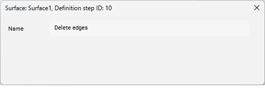
- Nazwa
- Wyświetla nazwę definicji powierzchni TIN: Usuń krawędzie.
Usuń zewnętrzne krawędzie
Definicja Usuń punkt usuwa trójkąty na zewnętrznej granicy powierzchni TIN, które mają:
- większa długość krawędzi
- Krótsza długość krawędzi
- większy kąt niż określony
Aby utworzyć definicję Usuń krawędzie zewnętrzne:
- Wybierz opcję Usuń krawędzie zewnętrzne w poleceniu TINEDYTUJ.
- Kliknij prawym przyciskiem myszy istniejącą powierzchnię TIN w panelu Eksplorator Civil i wybierz Usuń krawędzie zewnętrzne z grupy Edytuj.
Definicja Usuń krawędzie zewnętrzne jest automatycznie dodawana do powierzchni TIN po tej operacji.
Po dwukrotnym kliknięciu tej definicji na karcie Definicje w panelu Civil Eksplorator zostanie otwarte następujące okno dialogowe.
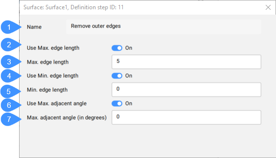
- Nazwa
- Użyj Maks. długość krawędzi
- Maks. długość krawędzi
- Użyj min. długość krawędzi
- Min. długość krawędzi
- Użyj Maks. kąta przyległego
- Maks. kąt przyległy (w stopniach)
- Nazwa
- Wyświetla nazwę definicji powierzchni: Usuń krawędzie zewnętrzne.
- Użyj Maks. długość krawędzi
- Przełącza użycie maksymalnej długości krawędzi.
- Maks. długość krawędzi
- Ustawia wartość maksymalnej długości krawędzi.Uwaga: Trójkąty z krawędzią przekraczającą określoną maksymalną długość krawędzi są usuwane z powierzchni TIN.
- Użyj min. długość krawędzi
- Przełącza użycie minimalnej długości krawędzi.
- Min. długość krawędzi
- Ustawia wartość minimalnej długości krawędzi.Uwaga: Trójkąty z krawędzią przekraczającą określoną minimalną długość krawędzi są usuwane z powierzchni TIN.
- Użyj Maks. kąta przyległego
- Przełącza użycie maksymalnego kąta przylegania.
- Maks. kąt przyległy (w stopniach)
- Ustawia wartość maksymalnego kąta przylegania.Uwaga: Trójkąty o kącie wewnętrznym przekraczającym określony maks. są usuwane z powierzchni TIN.
Minimalizacja płaskich obszarów
Definicja Minimalizuj płaskie obszary znajduje płaskie trójkąty, a następnie zamienia sąsiadujące krawędzie tych trójkątów tak, aby ich nachylenie było niezerowe.
Aby utworzyć definicję Minimalizuj płaskie obszary:
- Wybierz opcję Minimalizuj płaskie obszary w poleceniu TINEDYTUJ.
- Kliknij prawym przyciskiem myszy istniejącą powierzchnię TIN w panelu Eksplorator Civil i wybierz opcję Minimalizuj płaskie obszary z grupy Edytuj.
Po dwukrotnym kliknięciu tej definicji na karcie Definicje w panelu Civil Eksplorator zostanie otwarte następujące okno dialogowe.
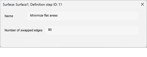
- Nazwa
- Wyświetla nazwę definicji powierzchni TIN: Minimalizuj płaskie obszary.
- Liczba zamienionych krawędzi
- Wyświetla liczbę zamienionych krawędzi na powierzchni TIN.
Usuń elewację
Ta definicja usuwa punkty TIN poniżej/powyżej określonej wysokości i wyświetla liczbę usuniętych punktów.
Aby utworzyć definicję Usuń punkty powyżej/poniżej wysokości:
- Wybierz opcję Usuń elewacje w poleceniu TINEDYTUJ.
- Kliknij prawym przyciskiem myszy istniejącą powierzchnię TIN w panelu Eksplorator Civil i wybierz Usuń elewację z grupy Edytuj.
Definicja Usuń krawędzie zewnętrzne jest automatycznie dodawana do powierzchni TIN po tej operacji.
Po dwukrotnym kliknięciu tej definicji na karcie Definicje w panelu Civil Eksplorator zostanie otwarte następujące okno dialogowe.
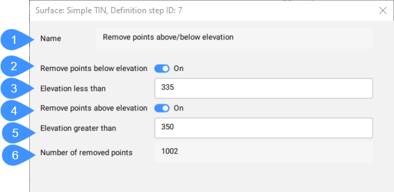
- Nazwa
- Usuń punkty poniżej rzędnej
- Wysokość mniejsza niż
- Usuń punkty powyżej wysokości
- Wysokość większa niż
- Liczba usuniętych punktów
- Nazwa
- Wyświetla nazwę definicji powierzchni: Usuń punkty powyżej/poniżej wysokości.
- Usuń punkty poniżej rzędnej
- Przełącza opcję usuwania punktów poniżej określonej wysokości.
- Wysokość mniejsza niż
- Ustawia wysokość, poniżej której punkty są usuwane.
- Usuń punkty powyżej wysokości
- Przełącza opcję usuwania punktów powyżej określonej wysokości.
- Wysokość większa niż
- Ustawia wysokość, powyżej której punkty są usuwane.
- Liczba usuniętych punktów
- Wyświetla liczbę usuniętych punktów.